Design pressure and design temperature selection
Warning
This is a non-exhaustive set of notes to aid selection of process design conditions. For use as an aide-memoir only. Always refer to local/client standards.
Equipment design pressure
Design pressure is the maximum and/or minimum pressure used to determine the mechanical design of equipment. The design pressure should therefore be dictated by the process system design.
Maximum design pressure
The maximum (or ‘upper’) design pressure is determined using the maximum operating pressures that can occur in the system. Generally the design pressure is determined by applying margins. Examples of such margins are given below and are often overridden by guidance from the operating entity/client standards.
- For max operating pressures ranging from full vacuum to 2.5 barg, a minimum upper design pressure of 3.5 barg is applied.
- For max operating pressures between 2.5 barg and 20 barg a 2 bar margin is applied.
- For max operating pressures above 20 barg a 10% margin is applied.
Minimum design pressure
Minimum design pressures are specified where sub-atmospheric pressures are expected in normal operation, during start-up activities, when there is utility failure, when the process is maloperated, where there are condensing services (including steam) with low vapour pressures, etc. For partial vacuums, the majority of the time we design for full vacuum unless this is not economically viable or this would not be compatible with other pipe features (e.g. lined pipe).
Full vacuum (often denoted as ‘FV’) should be specified for:
- all equipment and piping that contains steam.
- vessels containing boiling liquids where vapour pressure of the liquid < atmospheric pressure at the minimum ambient temperature.
- Cooling water pipework—vacuum can be pulled on pump trip, section drainage to grade or when isolating users located above the cooling tower cell inlet nozzle.
Additional considerations
Pumped systems
Design pressure downstream of a centrifugal pump is dictated by the maximum capability of the pump the system it is installed in.
When pump curves are not available (common during the design phase) one may estimate the shut-in head (at zero flow):
Also consider the affect of any variable speed drives.
Padded tanks
For gas blanketed vessels it is sometimes worthwhile to rate the vessel for the padding gas system design pressure as to eliminate the associated pressure relief breakthrough case (regulator failure etc).
Compression systems
Design pressure downstream of a centrifugal compressor is dictated by the maximum capability of the compressor. Design pressure should be equal to the relief set pressure on the upstream suction vessel plus the maximum head taken from the compressor performance curve. When curves are not available (common during the design phase) one may estimate the shut-in head (at zero flow):
The compression system settle-out condition (or equalisation pressure) must also be considered to check it is not higher than this. NB: the suction line will more than likely end up at the settle-out pressure upon shutdown/trip.
Equipment design temperature
Design temperature is the maximum and/or minimum temperature used to determine the mechanical design of equipment. The design temperature should therefore be dictated by the process system design. The design temperature may be less or equal to the Maximum Allowable Working Temperature (MAWT).
Maximum design temperature
Maximum (or ‘upper’) design temperature is determined using maximum operating temperature plus a margin of 25K, unless special situations apply (see below). Always double check against guidance from the operating entity/client standards.
Also consider the highest temperature that could be reached in a fault condition—though note that the fire case is excluded.
References that mention exlcusion of the fire case
…fire is generally not considered when evaluating pressure-relief requirements for piping… API 521 (7th edition) §4.4.12.4.1 (Hydraulic Expansion)
The fire scenario can result in either high-temperature vapors being discharged in the flare header and/or expose the flare header to the effects of the fire itself. It is common practice to exclude the fire-relief scenario when specifying the maximum design temperature of the flare headers. Regarding fire exposure, there may be situations where fire insulation of the header section(s) is warranted. It is up to the user to determine if and where fire insulation is provided. API 521 (7th edition) §5.5.13 (Setting the mechanical design temperature for flare headers)
Minimum design temperature
Minimum design temperatures are specified where sub-ambient temperatures are expected in normal operation, during start-up activities, upon utility failure, when the process is maloperated, etc. Auto refrigeration/Joule-Thompson effects should also be considered for liquefied gases when they are depressurised (i.e. pressure relief valve discharge lines). For example, when liquid chlorine is let down to atmospheric pressure, it will flash and will fall to roughly -34°C1.
The minimum design temperature should typically be specified as 5K below the minimum operating temperature, and at least equal to the minimum ambient temperature where the plant is located.
Additional considerations
Steam out
Steam-out conditions should be identified separately from design conditions. In the absence of client specifications consider using conditions of 140°C @ 1.5 barg / FV for steam out.
Relief valve laterals
The design temperature of a relief valve inlet line should be the same as that of the equipment it protects, and the design temperature of the relief valve outlet line should be same as the inlet line. However any auto-refrigeration effects—due to flashing across the relief valve—should be taken into account.
Chemical reactions
The design temperature of equipment/system where reactions take place should consider the maximum/minimum temperatures generated by runaway exothermic/endothermic reactions.
Loss of cooling
Consider loss of cooling flow when specifying systems downstream of heat exchangers (e.g. loss of cooling water). Downstream design temperature should not be less than the maximum upstream operating temperature.
Solar radiative heating
In scenarios where pipelines experience no flow, solar radiation can cause their temperature to surpass ambient levels. Industry guidance indicates that in such conditions, with still air and a maximum ambient temperature of 40°C, pipelines can reach an equilibrium temperature as high as 75°C.
Consideration should also be given to assigning a minimum design temperature of 75°C for all equipment and piping continuously exposed to intense sunlight.
Reference to temperature in API 521 (7th edition) §4.4.12.4.1
Where the system under consideration for thermal relief consists of piping only (does not contain pressure vessels or heat exchangers), a PRD might not be required to protect piping from thermal expansion if any of the following apply:
a) the piping always contains a pocket of noncondensing vapor, such that it can never become liquid-full; or
Caution—Small vapor or gas pockets can disappear upon heating due to compression and/or solubilization. In contrast, multicomponent mixtures with a wide boiling range can always have sufficient vapor present to preclude becoming completely liquid-full. The liquid-volume change upon solar heating, heat tracing, heating to ambient temperature, or heat from another source should be estimated to determine if the volume of the vapor pocket is sufficient for liquid expansion.
b) the piping is in continuous use (i.e. not batch or semicontinuous use) and drained after being blocked in using well supervised procedures or permits; or
c) the fluid temperature is greater than the maximum temperature expected from solar heating (usually approximately 60°C to 70°C (approximately 140°F to 160°F)) and there are no other heat sources such as heat tracing (note that fire is generally not considered when evaluating pressure-relief requirements for piping); or
d) the estimated pressure rise from thermal expansion is within the design limits of the equipment or piping.
Process piping
Design pressure
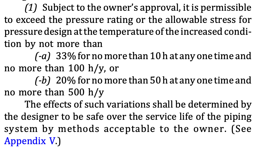
Lines normally inherit the design pressure of upstream equipment, but not always. If a scenario causing excessive design pressure arises infrequently and for a brief duration, ASME rules permit temporary pressures that exceed the line’s design pressure. This flexibility could enable specifying a lower design pressure and potentially using a less stringent pipe specification.
The relevant section of ASME Code for Pressure Piping B31.3 (§302.2.4) states:
Design temperature
Lines normally inherit the larger design temperature of upstream/downstream equipment, but not always.
For heat exchangers, the outlet line should match the temperature rating of the inlet line to accommodate loss of cooling. However, in situations like a steam desuperheater, this might be impractical and expensive. In such cases, an alternative is to install a short section of line downstream of the desuperheater rated for the inlet temperature, along with a high temperature alarm/trip to close the steam inlet valve upon detecting high temperature.
Changes in design conditions along a line
Design conditions may change along a line. e.g. upstream and downstream of a control valve, with a lower design pressure being acceptable downstream of the valve.
Footnotes
-
For chlorine in particular, consult Eurochlor guidance w.r.t design conditons. ↩