Centrifugal pump rundown time
Introduction
The rundown time is the time taken for the pump to decelerate from its normal operating speed to a complete stop after its power supply is lost or the pump is tripped. A longer rundown time maintains flow and discharge head for longer following a trip, reducing the rate of flow drop off and often the magnitude of surge. Conversely short rundown times cause rapid loss of head and potentially leading to larger pressure transients.
Following loss of power the pump continues to deliver flow, but both flow and pump head then decrease as its rotational speed drops. Rundown time depends on pump/motor inertia, hydraulic load, and frictional losses, and is an important parameter in surge assessments.
The formulae below used to estimate rundown time are contingent on the following assumptions:
- rundown of a centrifugal pump
- affinity laws can be applied (progressively more inaccurate at low speeds)
- valve positions remain unchanged
- incompressible liquid
- total inertia remains constant
- mechanical losses neglected
- hydraulic braking dominates
- only valid until the pump reaches zero rotational speed and does not model reverse rotation caused by reverse flow.
Nomenclature
| Symbol | Description | Units |
|---|---|---|
| Time elapsed since pump trip | s | |
| Euler integration timestep | s | |
| Shaft power at the current operating speed | kW | |
| Shaft power at the initial operating condition | kW | |
| Shaft (resisting) torque | N m | |
| Rotational inertia of the pump, impeller, shaft, and entrained liquid | kg m | |
| Rotational inertia of the motor rotor | kg m | |
| Total rotating inertia of the coupled system | kg m | |
| Angular velocity | rad s | |
| Initial angular velocity | rad s | |
| Angular acceleration (negative during rundown) | rad s | |
| Rotational speed | rpm | |
| Initial rotational speed | rpm | |
| Speed ratio, defined as | – |
Total rotating inertia
The rundown time of a centrifugal pump may be estimated by first estimating the total rotational inertia of the system. This must include all rotating components: the motor rotor, shaft, impeller, entrained liquid, coupling, and any other connected components. This is often quite difficult to get hold of for individual components, and the most accurate way to obtain the total figure is to source it from your manufacturer.
In lieu of vendor data, a statistical analysis of industry data in Fluid Transients in Pipeline Systems (Thorley) can be used to predict the total inertia
For a lot of systems this may estimated as:
The source of these individual terms and limitations are given below.
Pump inertia
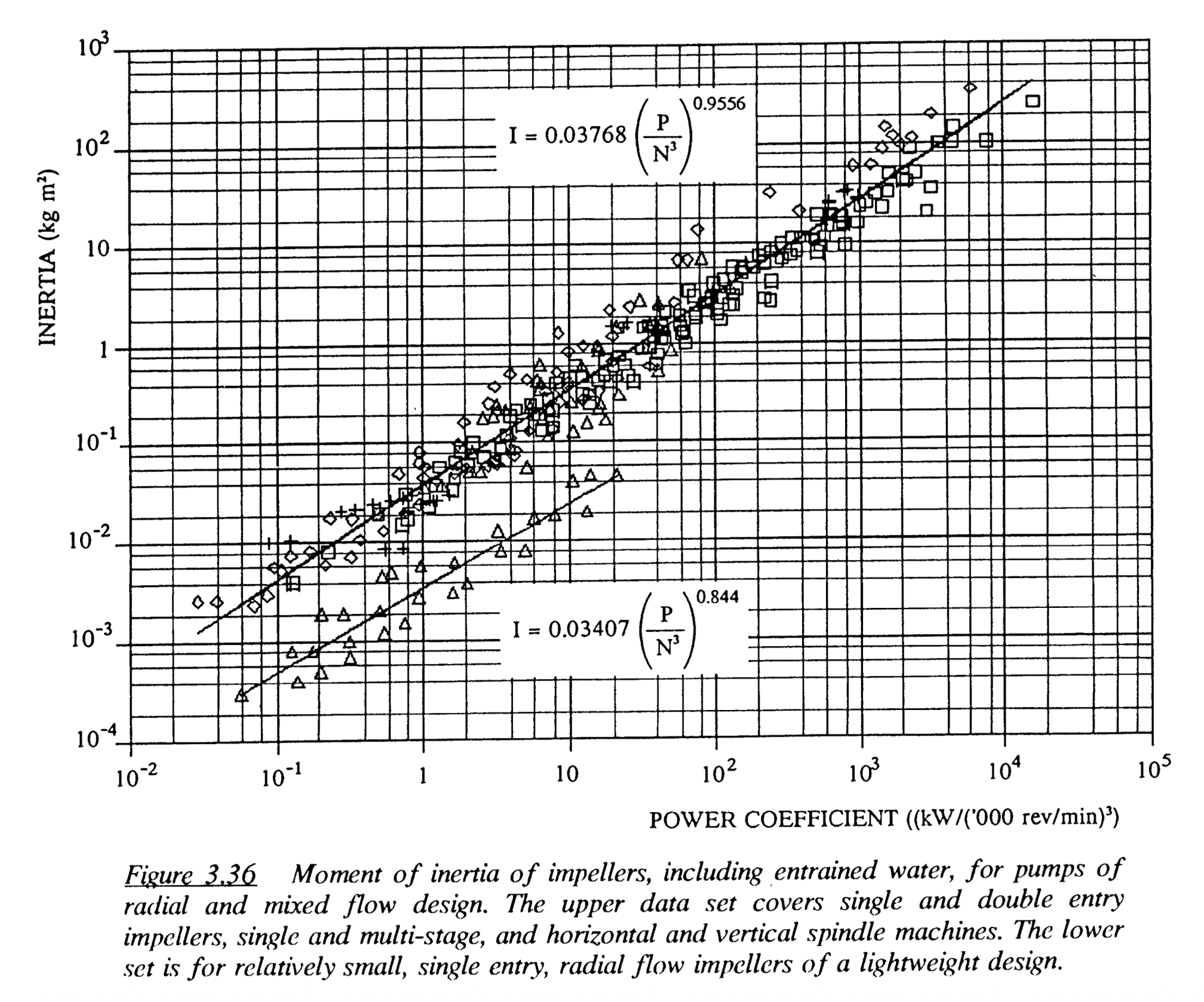
A linear regression of the two datasets analysed by Thorley give the following estimates of pump inertia for two different datasets.
A correlation for a wide range of rotodynamic pumps used in the water supply, sewage, process and petro-chemical fields, including horizontal spindle, single and double entry, split-case machines as well as vertical spindle borehole and wet-well pumps:
Another correlation is shown which applies to relatively small pumps of a lightweight design:
(both equations are adjusted to standard units: pump rotational inertia
Full dataset from Fluid Transients in Pipeline Systems (Thorley):
Warning
Use these inertia estimates with caution and apply margins where necessary when changes of pump speed are critical. Thorley notes:
Despite these apparently good correlations, it will be noted from observation of the graphs that the actual range of inertias above and below the predictions is of the order of +100 % and -50 %. This will only be important in those systems where the rate at which pumps change speed is significant, such as in networks or short pipelines of, say, 5 kilometres or less. This can easily be checked by doing an analysis with the predicted inertia, and then doubling and halving it.
Motor inertia
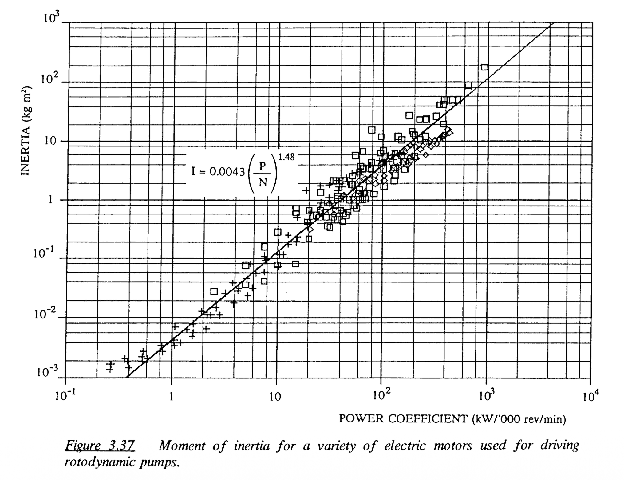
A linear regression of a datasets analysed by Thorley give the following estimate of motor inertia.
(equation adjusted to standard units: motor rotational inertia
Full dataset from Fluid Transients in Pipeline Systems (Thorley):
Rundown time estimate
Euler timestep method
Repeat over a constant timestep
- Known shaft speed.
- Calculate power (starting from shaft power at operating conditions).
- Calculate torque.
- Calculate deceleration.
- Calculate new speed.
- Repeat
Direct calculation of rundown time at a given final speed ratio
Power–torque relationship
From Newton’s second law for rotation, the net torque acting on a rotating system is equal to the product of total inertia and angular acceleration:
where
Angular acceleration is defined as:
Substitute into the torque balance:
For a centrifugal pump operating under affinity laws, power scales with the cube of rotational speed:
where
Substitute power into torque balance:
Integrating to find total rundown time:
Where